20W QRP Loop Antenna for HF Transceivers ICOM-705 5-30MHz 76-108MHz 110-150MHz
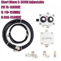
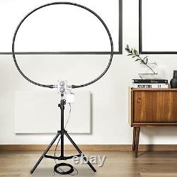
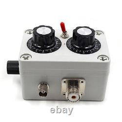
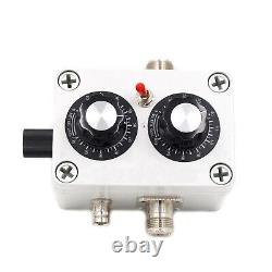
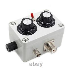
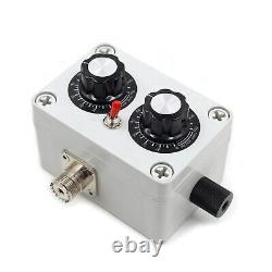
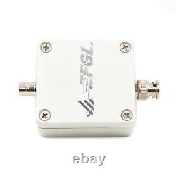
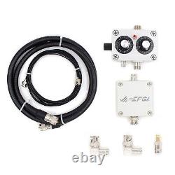

20w QRP Loop Antenna Loop Antenna for High Frequency Transceiver ICOM-705 5-30mhz 76-108mhz 110-150mhz 400 450mhz. This is a portable small loop antenna. It is easy and quick to set up the antenna for your shortwave transceiver antenna. Anti-interference, low standing wave, strong directivity, full frequency band.
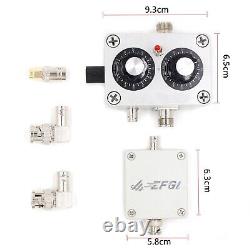
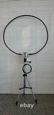
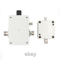
Thus, allowing you to enjoy multi-band reception and communication indoors, windows, balconies and outdoors. FM radio also provides excellent reception.Frequency band selection switch, pull up 7MHz, pull down 14-30MHz. The upper knob is the frequency tuning knob, and the frequency tuning value does not change due to environmental changes. The lower knob is the impedance matching knob, and the impedance matching value will change due to environmental changes. Use a right-angle adapter and a double male docking connector to connect the antenna to the M base on the back of the radio and stand it up or connect the ring body to the connection bases on both sides of the controller and tighten it, then install the tripod to the fixed base on the back of the tuner, open the tripod, place the antenna body firmly on the tripod, and finally connect the feeder (the feeder is attached with a choke, and one end of the choke is close to the small loop antenna). Now that the small loop antenna is connected to your station, you can now listen.
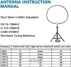
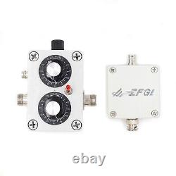
First, let's introduce the functions of the tuner panel. The toggle switch on the left is the frequency band selection switch (upper: 7MHz, lower: 14-30MHz).Main control knob, the upper knob is the frequency tuning knob, the frequency tuning value will not change due to environmental changes; the lower knob is the impedance matching knob, the impedance matching value will change due to environmental changes. (The adjustment range of the two knobs is 180 degrees, and the panel value is 0-12). When starting to use the radio, select the required frequency, then move the band switch to the required band position, then adjust the impedance matching value of the lower knob to 6, and then adjust the upper knob to tune. At this time, pay attention to the background noise of the radio station.
The more resonance there is, the greater the noise floor of the station. Since the knob of the portable version does not have a deceleration function, the fine-tuning method must be more delicate, and the smaller the rotation angle, the better.
At this time, obvious changes in the standing wave can be observed, but the minimum standing wave ratio is generally not less than 1.5. At this time, the impedance matching knob needs to be adjusted. It is recommended to randomly adjust plus or minus 5 scale values, and then repeat the steps of frequency tuning and observing the standing wave ratio. Due to the change of the matching value, there are two possibilities before comparison, 1: the minimum value of the standing wave ratio decreases; 2. The minimum value of the standing wave ratio increases.
If the minimum value of the standing wave ratio becomes lower, it means that the impedance matching adjustment is close to the correct value and further adjustments can be made. If the minimum value of the standing wave ratio becomes larger.
Repeat the above steps to adjust the antenna's VSWR to 1.0. For VHF and UHF frequency bands, the upper knob is fixed to 12, and the lower knob can appropriately adjust the impedance resonance. Note: It is best to use it outdoors. The antenna should be used indoors as close to the window as possible, in a fully enclosed environment with reinforced concrete, or against a wall. The standing wave ratio in some frequency bands is not ideal. Advanced tips: When the signal is weak, you can rotate the antenna direction to improve the signal-to-noise ratio and facilitate reception. The loop antenna's unique gain lobe gives it horizontal gain directivity when upright. Using its characteristics, multiple signals in the horizontal direction can be selected in a targeted manner, and co-channel interference in the horizontal direction can also be reduced. Of course, if the interference signal is extremely strong and is much larger than the useful signal that needs to be received, the attenuation effect will not be too obvious.Compared with the telescopic antenna, it can still play a weakening effect. Short wave: 5 30 MHz adjustable. V band + aviation band: 110150MHz. U segment: 400 450 MHz.
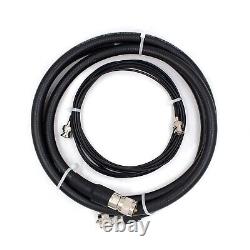
1X5 meters 50 ohm coaxial cable.
