HG-20A 20W QRP Loop Antenna for HF ICOM-705 5-30MHz 76-108MHz 110-150MHz
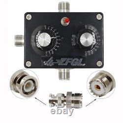
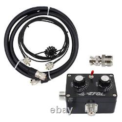

If you have any questions, please contact customer service first, do not open disputes easily, thank you! This is a portable small loop antenna. It is easy and fast to set up the antenna for your shortwave transceiver antenna. Anti-interference, low standing wave, strong directionality and full band frequency.
So let you enjoy multi-band reception and communication indoors, windows, balconies and out. FM FM radio also provides excellent reception. Frequency band selector switch, pull up 7MHz, pull down 14-30MHz. The upper knob is the frequency tuning knob, the frequency tuning value does not change according to the environment. The lower knob is the impedance matching knob, the impedance matching value will change due to environmental changes.
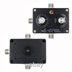
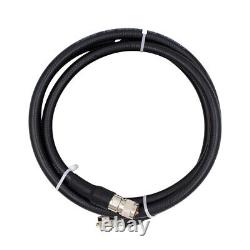
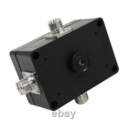
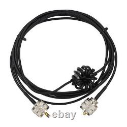
FM tuned radio also provides excellent reception. Use right angle adapter and double male butt to connect the antenna to the m-mount on the back of the radio and stand it up or connect the loop body to the connecting mounts on both sides of the controller and tighten it up, then mount the tripod to the fixed mount on the back of the tuner, open the tripod and place the antenna body firmly on the tripod, and lastly, connect the feeder cable (the feeder cable is attached with a choke, the end of the choke is close to the small loop antenna). Now that the small loop antenna is connected to your station, you are now ready to listen. Firstly the functions of the tuner panel, the toggle switch on the left is the band selector switch (top: 7MHz, bottom: 14-30MHz). The main control knob, the upper knob is the frequency tuning knob, the frequency tuning value will not change due to environmental changes; the lower knob is the impedance matching knob, the impedance matching value will change due to environmental changes.
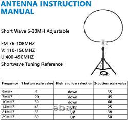
(Both knobs have an adjustment range of 180 degrees and panel values of 0-12). To start using the radio, select the desired frequency, then flick the band switch to the desired band position, then adjust the impedance matching value of the lower knob to 6, and then adjust the upper knob for tuning. At this point, pay attention to the radio's bottom noise.
The more resonance there is, the greater the radio's bottom noise will be. Since the knob of the portable version does not have a deceleration function, the fine-tuning method must be more delicate, and the smaller the rotation angle, the better. At this time, you can observe a significant change in standing wave, but the minimum standing wave ratio is generally not less than 1.5. This time you need to adjust the impedance matching knob. It is recommended to randomly adjust plus or minus 5 scale values, and then repeat the steps of frequency tuning and observing the VSWR. As the matching value changes, there are two possibilities before comparing, 1: the minimum value of the VSWR decreases; 2: the minimum value of the VSWR increases. If the minimum value of the VSWR becomes lower, it means that the impedance matching adjustment is close to the correct value and can be further adjusted. If the minimum value of the VSWR becomes large.Repeat the above steps to adjust the antenna's VSWR to 1.0. For VHF and UHF bands, the upper knob is fixed to 12 to the bottom, and the lower knob can adjust the impedance resonance appropriately. Outdoor use is best, indoor use of the antenna as close as possible to the window, reinforced concrete fully enclosed environment, against the wall and other environments, part of the band VSWR is not ideal. When the signal is weak, you can rotate the antenna direction to improve the signal-to-noise ratio, which is conducive to reception. The unique gain flap of the loop antenna makes it have horizontal gain directionality when it is upright.
Using its characteristics, you can target multiple signals in the horizontal direction and also reduce co-channel interference in the horizontal direction. Of course, if the interference signal is extremely strong, much larger than the useful signal to be received, the attenuation effect will not be too obvious, compared to the telescopic antenna can still play a role in attenuation. Tripod stand is not included.
