PAC12 mini 7MHz-50MHz 100W Multi Band HF Shortwave GP Antenna QRP For Ham Radio
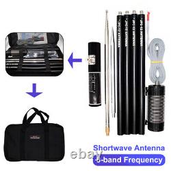
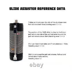
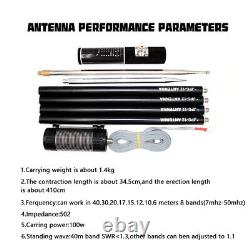

Packaging weight: approximately 1.35kg Packaging size: 36 22 4cm. The contraction length is about 34.5cm, and the erection length is about 410cm. Frequency: It can operate in 8 bands (7mhz-50mhz) from 40.30 to 20.17 to 15.12 to 10.6 meters. Longitudinal wave: 40m SWR band. S liding regulator reference data.
Close to the aluminum tube for 4 turns and 7mb, with the pull rod retracted by about 10cm and the foot wave 1.1-1.3. The position of the 14mb slider is close to the side of the rod antenna, and it is pulled back about 20cm in 6 circles. Foot waves 1.1-1.3.
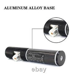
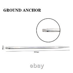
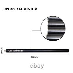
21.4 Aluminum tube and 4-pole antenna, 7-10cm, vertical wave 1.1-1.3. 29.6 Just pull the antenna out of the pole, everyone pull it back about half a section, standing wave 1.2. An aluminum alloy base (anodized to black). Multi band additive coil (40m-10m, material: nylon, note: additive coil is not manufactured). One ground anchor, size 10.
240mm (maintain good grounding without electroplating). 4 aluminum oxide tubes (black), size 19. 2.5m 1 stainless steel rod top antenna (custom thickened). A 10 wire mesh ground wire (usually tear 3 wires as needed). No te : There is no paper feeder, which saves energy and does not require a paper manual. Place the grounding grid connecting ring directly on the screw of the anchor and screw it into the base. Then there is the link base, four aluminum tubes, inductance coils, and rod antennas in sequence. In the case of standing wave adjustment and with a talent meter, first find the lowest point of the standing wave and see if the resonance frequency is high or low. If the resonance frequency is high, it indicates that the antenna is short. It is necessary to lengthen the rod antenna or increase the number of coils of the induction coil. If it is low, shorten the rod antenna or reduce the number of coils of the induction coil antenna. When using the grounding net, tear apart 3-4 pieces. Adjusting the angle of the grounding grid can change the antenna impedance.
